Seafloor
Hazards
A team approach to
mitigating shallow water flow risk
Since two
wells were previously abandoned at Mississippi Canyon 849, a
team of geohazards specialists alleviated the risk, allowing
the drilling of a successful exploration well
Robert Bruce, Noble Energy,
Inc., James McKeown, Fugro GeoServices, Inc., Tim
Sargent, Noble Energy, Inc., Randal Garrett, Sierra
Engineering
Wells drilled near the Mars, Ursa
and Europa basins within the Mississippi Canyon Area, Gulf of
Mexico, have experienced varying degrees of shallow water flow
problems. Two wells drilled in Mississippi Canyon Block 849
(MC 849) penetrated overpressured sands within the shallow
section, causing catastrophic shallow water flow. Both wells
were subsequently abandoned. A team of geohazards specialists,
geologists, geophysicists and engineers worked together to
identify and mitigate this SWF, and successfully drilled the
Slam Dunk exploration well in MC 849.
INTRODUCTION
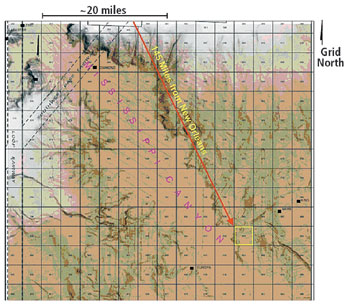
Mississippi Canyon Block 849 is
located 145 mi southeast of New Orleans, Louisiana, in about
3,600 ft of water, Fig.1. The Pliocene target of the two wells
previously drilled on the block, the Norcen-1 and UPRC-2, is a
well-defined series of vertically stacked amplitudes within a
thickening wedge of seismic reflectors. These amplitudes are
stratigraphically trapped on the flank of a large salt ridge,
which separates the prospect from the Mars basin to the east.
While attempting to drill this prospect, both wells were lost
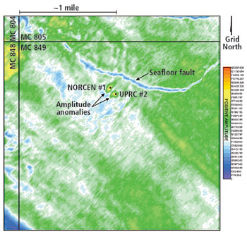
due to shallow water flow (SWF). A seafloor amplitude map
generated from a subsequent 3D geophysical survey by TGS over
MC 849 showed areas of high seafloor amplitude around the
Norcen and UPRC wells, which were interpreted to represent
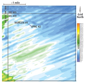
sand "mined" by the SWF. These areas are not visible in the
original 3D seismic data acquired by Western Geophysical
(Figs. 2 and 3). The SWF encountered at the Norcen and UPRC
wells was so severe that during the planning of the Slam Dunk
prospect, it was debated if drilling a successful well was
feasible.
 |
|
Fig. 1. Seafloor
rendering showing Mississippi Canyon and MC Block
849.
| |
 |
|
Fig. 2. Seafloor
amplitudes showing amplitude anomalies at the
Norcen and UPRC wellsites.
| |
 |
|
Fig. 3. Seafloor
amplitude map prior to drilling of Norcen and UPRC
wells.
| |
SWF is defined as water or sand and
water flowing within and around the outside of structural well
casing to the seafloor. 1 Isolating the specific
stratigraphic interval where SWF was previously reported, and
delineating the extent and distribution of the potential SWF
sands were key factors in reducing the risk of encountering
SWF at the Slam Dunk prospect.
DATA SETS
The geohazards investigation was
based on interpretation of reprocessed 3D seismic exploration
data acquired by TGS. The 3D data cube contained 2-ms
sample-rate data to a record length of 3.5 sec. TWT below sea
surface. The exploration data was reprocessed with spectral
whitening to enhance the higher frequencies in the tophole
section. The dominant frequency of the 3D seismic data set was
estimated to be about 50 Hz in the shallow section, which
corresponds to a limit of separability of about 27.5 ft,
assuming an average velocity of 5,500 ft/sec for the shallow
sediments.
Offset well data provided for this
study included LWD logs from the Norcen and UPRC wells, which
allowed geophysical correlation to the proposed Slam Dunk
prospect. Digital versions of the LWD logs were provided and
integrated into the 3D seismic data with a velocity function
generated for the Slam Dunk prospect. Drilling reports from
the Norcen and UPRC wells were also utilized.
THE MISSISSIPPI FAN
The Mississippi Fan is part of a
larger accumulation of sediments deposited by the Mississippi
River system during the late Pliocene and Pleistocene along
the outer shelf, slope, and deep basin of the eastern Gulf of
Mexico during glacial low-stands of sea level. Complex seismic
facies within the fan reflects deposition by a wide variety of
processes including turbidites, mass transport complexes,
slumps, channel deposits and channel-overbank deposits.
Primary fan deposition is apparently related to submarine
canyons that cut across the slope and funneled sediments to
the deep basin. The Mississippi Canyon is the youngest of
these canyon systems. This canyon formed about 25,000 - 27,000
years B.P. and infilling commenced about 20,000 years B.P. The
canyon, therefore, formed in a very short time, removing a
minimum of 1,500 - 2,000 km 3 of materials in about
7,000 years. 2
Large-scale slumping on an unstable
continental shelf-slope area represents the best explanation
for the formation of the canyon based largely on the many
large cuspate failure scars along the canyon walls. Some of
the sediment masses on the present canyon floor can be traced
back to those scars. 3 Thus, the Mississippi Canyon
resulted from shelf-edge failures, followed by retrogressive
slumping of shelf material around canyon margins. Rapid shelf
progradation during lowering sea level probably produced a
large mass of rather weak sediments. During the period 10,000
- 20,000 years B.P., a series of Late Wisconsin delta lobes
almost filled the canyon with prodelta clays. 3
Hemipelagic sedimentation has been dominant during the last
10,000 years, and probably accounts for only tens of feet or
less of the Quaternary section of the fan.
Multifold industry seismic data
confirm this interpretation of the formation of the
Mississippi Canyon and the depositional history of the
Mississippi Fan. The availability of a relatively dense grid
of industry multifold seismic data has allowed for a much more
detailed analysis of the Middle Fan lying just south of the
deformed slope. 4 In this area, 17 Quaternary
sequences have been defined and mapped, each characterized by
channel-levee-overbank systems.
Cyclic depositional patterns within
each sequence probably reflect deposition in response to
Pleistocene sea-level cycles. The lower, less organized
seismic facies represent sediment eroded from submarine
canyons during the fall in sea level, while the more organized
channel-levee-overbank facies represent material funneled
directly down the canyons to the deep basin during low stands
and the following rise. The most recent lowstand was about
15,000 years ago and reached a minimum level near the shelf
break at about 500 - 600 ft below present sea level.
5 Near present sea level was reached about 7,000 years
ago.
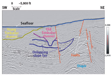
At MC 849, two buried-channel
complexes occur in the shallow stratigraphy within 2,000 ft
below the water bottom. The most recent is the Young Timbalier
Channel Complex, which underlies the Mississippi Canyon floor
and has seafloor expression. Deeper in the section, is the Old
Timbalier Channel, which extends from the northwest to the
southeast through MC 849 and is probably composed of multiple
cut-and-fill episodes that have crossed this part of the upper
slope, Fig. 4.
 |
|
Fig. 4. 3D
seismic data example showing shallow geologic
features within study area.
| |
Deposition within the channels is
very complex and variable, while some internal side-wall
slumping of sand-prone strata toward the channel axis
(thalweg) may have occurred during and after channel
depositional events. The Old Timbalier Channel was probably a
high-velocity system, as evidenced by its straight, relatively
deep channel, Fig. 5. As a result, coarse-grained sediments
may not have settled out of suspension within the portion of
the channel that transects MC 849, and may have been deposited
further down slope.
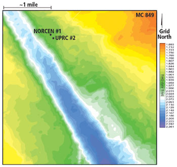 |
|
Fig. 5. 3D
seismic data example showing Old Timbalier Channel
incision through MC 849.
| |
Underlying the Old Timbalier
Channel Complex is an onlapping slope fan sequence. The fan
steepens to the southeast and onlaps a diapiric ridge in the
northern portion of the MC 849. A portion of this upper fan
sequence was removed by the incision of the Old Timbalier
Channel, Fig. 4. The fan is interpreted as a predominantly
sand-prone unit. Seismically, the fan exhibits low-to-high
amplitude, subparallel, discontinuous and chaotic
reflectors.
SHALLOW SUBSURFACE
GEOLOGY
Four subsurface horizons (10, 20,
30 and 40) were mapped in MC Block 849 to a depth limit of 1
sec TWT (~2,860 ft) below water bottom. These horizons
separate four stratigraphic sequences (1 through 4) of
distinct seismic and inferred lithologic character. Gamma ray
and resistivity LWD logs from the Norcen and UPRC wells were
correlated with the 3D seismic data and used to calibrate the
lithologic interpretation of the shallow section in the
vicinity of the proposed Slam Dunk wellsite.
Sequence 1 consists of mostly
undisturbed, continuous parallel-stratified hemipelagic clays.
Sequence 2 is interpreted to represent parallel-stratified
clays with some interbedded sand-prone intervals and thin
landslide deposits. The gamma ray logs indicate that the lower
portion of Sequence 2 exhibits a fining-upward, sand-prone
character. These wells were drilled along the northwestern
margin of the Old Timbalier Channel. However, within the
thalweg of the Old Timbalier Channel, reflectors display a
low-to-moderate amplitude, discontinuous-to-chaotic character,
interpreted as predominantly clay-prone deposits with some
sandy lenses.
Within Sequence 2, as the Old
Timbalier Channel incised into the underlying sand-prone slope
fan, coarse-grained sediments may have been deposited through
channel-margin failure. The steep, straight and, thus,
high-velocity nature of the Old Timbalier Channel (Fig. 5), as
well as the lack of high amplitude internal reflectors,
suggests that coarser-grained sediments were probably
deposited farther downslope of MC 849.
Sequence 3 is divided into upper
and lower units. The upper unit of Sequence 3 comprises
sand-prone slope fan deposits. The gamma ray and resistivity
logs indicate sand-prone deposits within upper Sequence 3. The
lower unit of Sequence 3 is interpreted as predominantly
fine-grained submarine landslide/ debris flow deposits that
may contain thin, discontinuous sands. Sequence 4 comprises
fine-grained landslide/ debris flow deposits with some
discontinuous sands. The gamma ray and resistivity logs
indicate primarily clay-prone deposits with some interbedded
sands within lower Sequence 3 and Sequence 4.
ISOLATING THE PROBLEM
After reviewing the drilling data
from the Norcen and UPRC wells and tying the well logs to the
3D seismic data, it was evident that the Old Timbalier Channel
margins and the slope fan sequence presented the greatest
potential for SWF. SWF was first observed in the Norcen well
within a seismically dim sand-prone interval within Sequence 2
at about 4,600 ft below sea surface. SWF was observed in the
UPRC well at the 20-in. casing annulus, which was open to the
Sequence 2 sand interval. The slope fan sequence below the Old
Timbalier Channel incision (Figs. 4 and 5) was also assessed
as having a high potential for overpressure due to its
interpreted high sand content and rapidly deposited,
clay-prone overburden.
Sequence 2 sand. SWF began
at the Sequence 2 sand in the Norcen well. The LWD logs and
drilling reports from the Norcen and UPRC wells indicate a
thin sand at about 4,600 ft below sea surface (~1,000 ft BML).
In the 3D seismic, this interval correlates to a seismically
dim trough reflector in Sequence 2 above the Old Timbalier
Channel incision. The seismic attributes of this sand
initially implied that it was potentially sand-starved, poorly
developed and laterally truncated. However, current research
indicates that it is difficult to seismically image SWF sands
due to the relatively low sand/ shale contrast in acoustic
impedance in the shallow section, 6 Fig. 7.
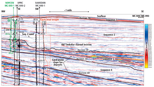 |
|
Fig. 7. 3D
seismic record showing seismic/ well log
correlation at MC 849 wellsites.
| |
A 3D amplitude map of the Sequence
2 sand indicates what appears to be a channel levee
depositional system, Fig. 6. The Norcen and UPRC wells are
located in relatively higher amplitude associated with the
levee on the northeastern margin of the system. There is a
large, relatively dim amplitude area associated with the
thalweg of the Old Timbalier Channel, indicating either the
absence of, or poorly developed, Sequence 2 sand.
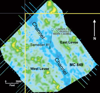 |
|
Fig. 6.
Amplitude map of Sequence 2 sand showing channel/
levee complex.
| |
Slope fan sequence. The
slope fan sequence comprises subparallel, discontinuous and
chaotic, low-to-high amplitude reflectors interpreted to
represent a sand-prone slope fan with some interbedded
clay-prone deposits. Gamma ray logs support this
interpretation, but display a clay-prone response in the lower
portion of the sequence (Fig. 4). This fan onlaps a salt
diapir in northern MC 849, and slopes to the southeast. A
portion of the fan has been removed by channeling events
associated with the Old Timbalier Channel, which extends
through MC 849 from the northwest to southeast (Figs. 4 and
5). This package is approximately 250 milliseconds thick at
the Norcen and UPRC wells (Fig. 7). In the 3D seismic, the
slope fan dips to the south at a high angle as the interval
thickens dramatically.
MITIGATING THE RISKS
After identifying the potential SWF
intervals, a plan was developed to mitigate the risk.
Accordingly, corrective measures would be taken to ensure that
overpressured zones, if encountered, would not be allowed to
flow. Mitigating the SWF potential while drilling would yield
a stable wellbore and aid in successful cement isolation of
the SWF zones. Additionally, it was recognized that if an SWF
was encountered it would likely cause wellbore enlargement and
undermining of the surrounding formation. SWF containment in
this situation is problematic, with catastrophic wellbore
failure common. Once SWF started at the Norcen and UPRC wells,
it could not be controlled, and the wells were subsequently
plugged and abandoned.
The drilling data from the Norcen
and UPRC wells did not indicate whether the SWF was confined
to the Sequence 2 sand or if there was additional flow from
the deeper slope fan sequence (Figs. 4 and 7). Due to the
interpreted high sand content, it was assumed that the slope
fan could have contributed to the SWFs in both the Norcen and
UPRC wells. Therefore, penetrating the slope fan sequence at
its thinnest incised point would be favorable. Based on the
drilling data, and due to the catastrophic nature of the SWF
encountered at the Norcen and UPRC wells, the greatest SWF
risk and drilling challenge was determined to be the Sequence
2 sand. It was believed that flow initiated in that sand and,
once penetrated, the slope fan sequence could also flow. It
was assumed that if these problematic zones began flowing, it
would not be possible to contain them.
At the Norcen well, it was believed
that the initial flow from the Sequence 2 sand undermined the
surrounding formation causing a large washout in the wellbore,
which contributed to insufficient isolation of the 20-in.
casing annulus. Since the wellhead annulus was not sealed, the
flow was able to continue unabated.
The UPRC well was drilled through
the Sequence 2 sand with no indications of flow out of the
20-in. casing annulus until after the 16-in. casing was
cemented below the slope fan sequence. The flow continued
outside the 20-in. casing while the well was drilled to a
total depth of 8,606 ft below sea surface. The 16-in. casing
shoe was cement squeezed and a subsequent casing test proved
unsuccessful. Communication with the existing flow behind the
20-in. casing indicated a mechanical failure of the 16-in.
hanger seal or a casing connection, adding uncertainty as to
whether the SWF was only from the Sequence 2 sand.
An amplitude map generated on the
Sequence 2 sand indicated a channel/ levee depositional
system, Fig. 6. The lack of relatively high amplitude within
the thalweg of the Old Timbalier Channel was interpreted as
relatively sand-poor deposition, which would eliminate much of
the risk of SWF from the Sequence 2 sand interval. The
straight, high-velocity nature of the Old Timbalier Channel
was interpreted to have transported coarser-grained sediments
farther downslope leaving the thalweg primarily clay-filled.
The Old Timbalier Channel was sufficiently close to the
prospect targets and would not require a high-angle
directional well to test the prospect. Additionally, a surface
location to the southwest and within the Old Timbalier Channel
thalweg provided enough distance from the Norcen and UPRC
wells to eliminate possible problems with higher pressured
intervals associated with the SWF. Based on drilling data from
the Norcen and UPRC wells, the slope fan interval presented
the second highest risk for SWF. The slope fan dips to the
southeast at about 28° to 30° and thickens dramatically
basinward, giving the sands in this location the potential for
increased hydraulic pressure from the basin to the
south.
Within MC 849, the entire slope fan
is incised by Old Timbalier Channel unconformity. The Slam
Dunk surface location would have to "thread the needle"
through the intervals identified as having high risk for SWF,
penetrating each interval in the lowest risk position
possible. A location 3,000 ft to the southwest of the Norcen
and UPRC wells satisfied these criteria. At this location, the
well would be in the thalweg of the Old Timbalier Channel and
within an area of low Sequence 2 sand amplitude, interpreted
as having the least sand potential. Also, it would be
significantly down dip and far enough away from the Norcen and
UPRC wells.
Two locations were permitted within
1,500 ft of each other. The rig would set up between the two
locations and set anchors. Once anchors were set, the rig
could then winch to the "A" location and drill. If problems
were encountered, it would be possible to winch the rig to the
second permitted location without having to re-set
anchors.
SHALLOW SECTION WELL
DESIGN
The well design and operational
plan for drilling through the shallow section focused on
eliminating any SWF and lost circulation events. All available
drilling data from the Norcen and UPRC wells, including LWD
and pressure-while-drilling (PWD) information was analyzed for
SWF and mud loss limitations. A favorable surface location was
chosen which minimized the risk of SWF, while casing points
were selected according to pore pressure and fracture gradient
estimates as calibrated from the offset wells. Both the Norcen
and UPRC wells flowed behind the 20-in. casing after
cementing. As a result, emphasis was placed on casing design,
cement seal design, and annulus sealing wellhead equipment for
the Slam Dunk wellsite.
The Slam Dunk casing program
required "jetting-in" the 36-in. conductor casing to 300 ft
below water bottom for added wellhead structural stability.
The 26-in. casing was set at 1,000 ft below water bottom in
order to "top set" the Sequence 2 sand interval. The 26-in.
casing was cemented using nitrified cement with 150% annulus
excess to ensure returns to the surface. The SWF intervals
were planned to be drilled using a riserless mud drilling
technique ("pump and dump"), taking mud returns at the
seafloor. The use of 11.2 ppg mud, in conjunction with the
seawater gradient above the wellhead, yielded a hydrostatic
equivalent of 9.8 ppg at TD and 9.3 ppg at the Sequence 2 sand
interval, which was sufficient to contain the higher pressures
within the SWF interval. Cement calculations were planned for
150% annulus excess to ensure returns to the seafloor using
nitrified cement. To help eliminate possible "behind pipe"
flow after cementing, a wellhead with four annular ball-valves
was utilized. After cementing, the ball-valves were closed,
thus greatly reducing the risk of an SWF.
CONCLUSIONS
After repeated attempts to drill
the Pliocene prospect in MC 849, the Slam Dunk well was
drilled as designed, under budget, and without SWF or
loss-of-return events. The gamma ray and resistivity logs
through the shallow section at the Slam Dunk well indicated
very little sand development, especially within the Sequence 2
interval. The relatively high amplitude of the Sequence 2 sand
along the Old Timbalier channel margins (Fig. 6) was
representative of well-developed channel/ levee sands capable
of SWF, while the channel thalweg was predominantly
clay-prone, Fig. 7.
This project emphasizes the
importance of a multi-disciplined team working together to
successfully overcome potentially catastrophic events. This
synergistic approach is becoming more essential as oil
companies move into deeper water where well costs are
high.

ACKNOWLEDGMENTS
3D seismic data examples are
courtesy of TGS and Western Geophysical. Ralph Baird of
Baird Petrophysical Int'l. Inc. provided the velocity
function for the shallow subsurface. Thanks to Noble Energy,
Inc., and Fugro GeoServices Inc. for permission to publish
this paper. This article derives from OTC15249, which was
presented at the 2003 Offshore Technology Conference held in
Houston, Texas, May 5 - 8, 2003, and is presented with
permission.
LITERATURE
CITED
1 Alberty, M. W., M.
E. Hafle, J. C. Minge and T. M. Byrd, "Mechanisms of shallow
waterflows and drilling practices for intervention,"
Proceedings, Offshore Tech. Conference , OTC 8301,
1997.
2 Bouma, A. H., C. E.
Stelting and J. M. Coleman, "Mississippi Fan: Internal
structure and depositional processes," Geo-Marine
Letters , v. 3, pp. 147 - 153, 1984.
3 Coleman, J. M., D.
B. Prior and J. F. Lindsay, "Deltaic influences on shelf
edge instability processes," in D.J. Stanley and G.T. Moore
(eds.), The shelf break, critical interface on continental
margins. Society of Economic Paleontologists and
Mineralogists Special Publication, Vol. 33, pp. 121 -
137, 1983.
4 Weimer, P. "Sequence
Stratigraphy, Facies Geometries, and Depositional History of
the Mississippi Fan, Gulf of Mexico: American
Association of Petroleum Geologists Bulletin , Vol. 74,
pp. 425 - 453, 1990.
5 Ballard, R. C., and
E. Uchupi, "Morphology and Quaternary history of the
continental shelf in the Gulf Coast of the United
States," Marine Science , Vol. 20, pp. 542 - 549,
1970.
6 Ostermeier, R. M.,
Pelletier, et al., "Dealing with shallow-water flow in the
deepwater Gulf of Mexico" The Leading Edge , Vol.
21, pp. 660 - 668, 2002.
|
THE
AUTHORS |
 |
Robert C. Bruce earned
a BS degree in geology from The College of Charleston,
Charleston, South Carolina. He is primarily a prospect
generator but is also responsible for hazard
interpretation and SWF problems. He is currently a
geophysical advisor in the Deep Water Business Unit of
Noble Energy, Inc., in Houston. He is a member of SEG
and AAPG and is a licensed geologist. |
 |
James M. McKeown holds
an MS degree in geology from The University of
Mississippi, Oxford, Mississippi, and is a licensed
geologist in Texas. He is currently a project geologist
with Fugro GeoServices, Inc., in Houston, where he is
responsible for interpretation and mapping of 3D seismic
exploration data and 2D high-resolution geophysical
data, to assess potential geologic hazards and to
predict conditions in the tophole section.
|
| |
Tim Sargent earned a
BSME degree in 1975 from Clemson University and
immediately began his career in the oil industry at
Amoco Production Co. Tim is currently employed at Noble
Energy, Inc. as a sr. engineering advisor with
supervisory responsibilities for GOM Deepwater and Shelf
projects involving drilling, completion, or workover
operations.
| |
